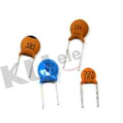
|
1.FEATURES & APPLICATIONS
|
|
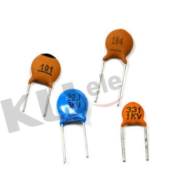
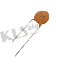
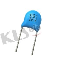
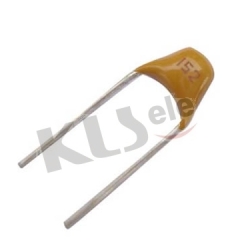
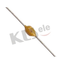
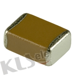
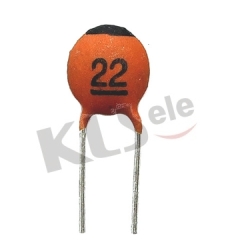
This disc ceramic capacitors belong to surface layer semi-conductive construction,
have characteristics such as higher capacitance ,small size etc..They are suitably
used in bypass cuicuit,coupling circuit,filter circuit and isolating circuit etc..
|
2.SPECIFICATIONS
|
capacitance |
0.01μF~0.22μF |
| capacitance tolerance |
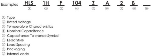
K(±10%),M(±20%),Z(+80% -20%) |
| operating temperature |
-25℃~85℃ |
| temperature characteristic |
Y5P,Y5U,Y5V |
| rated voltage |
16VDC,25VDC,50VDC |
| dissipation factor(tgδ) |
16V: tgδ≤7%
25V,50V:tgδ≤3.5%(Y5P),tgδ≤5%(Y5U,Y5V)
@ 1KHz,1±0.2Vrms,25℃ |
| insulation resistance(IR) |
16V: IR≥100MΩ
25V: IR≥250MΩ
50V: IR≥1000MΩ |
| voltage proof |
1.5Ur |
| testing voltage |
2 times the rated voltage |
|
3.CAPACITANCE CHART
rated
voltage |
dimension |
temperature characteristic |
lead size |
| (VDC) |
dia. |
thick |
Y5P(B) |
Y5U(E) |
Y5V(F) |
space |
diameter |
| cap. |
Plate Size |
cap. |
plate size |
cap. |
plate
size |
| 16 |
5.5 |
4.0 |
|
|
|
|
683~104 |
5320 |
2.5±0.8 |
0.40±0.05 |
| 6.0 |
|
|
|
|
683~104 |
5620 |
5.0±1.0 |
0.45±0.05 |
| 6.5 |
|
|
|
6225 |
|
|
| 7.5 |
|
|
|
|
124~154 |
7020 |
| 8.5 |
|
|
|
|
204~224 |
8030 |
| 25 |
4.0 |
|
|
|
|
103~473 |
3816 |
2.5±0.8 |
0.40±0.05 |
| 4.5 |
|
|
153~223 |
4225 |
|
|
| 5.0 |
|
|
333 |
4625 |
|
|
| 6.0 |
|
|
473 |
5625 |
683~104 |
5625 |
5.0±1.0 |
0.45±0.05 |
| 6.5 |
|
|
|
|
683~104 |
6025 |
| 7.5 |
|
|
683~104 |
7025 |
|
|
| 8.5 |
|
|
|
|
224 |
8030 |
0.53±0.05 |
| 11.0 |
104 |
10330 |
|
|
|
|
| 50 |
4.0 |
|
|
103 |
3816 |
153~223 |
3826 |
2.5±0.8 |
0.40±0.05 |
| 4.5 |
|
|
153~223 |
4225 |
|
|
| 5.0 |
103 |
4625 |
333 |
4625 |
133~473 |
4625 |
| 6.0 |
153~223 |
5625 |
473 |
5625 |
683 |
5625 |
5.0±1.0 |
0.45±0.05 |
| 7.5 |
333 |
7025 |
|
|
104 |
7025 |
| 8.5 |
473 |
8030 |
683~104 |
8030 |
154 |
8030 |
0.53±0.05 |
| 9.5 |
|
|
|
|
224 |
9030 |
| 12.0 |
104 |
11035 |
|
|
|
|
| capacitance tolerance |
±10% |
±20% |
+80/-20%,+50/-20% |
|
|
| packing style |
bulk,taping |
|
|
|
4.Class Ⅱ & ⅢCeramic Capacitors
Codes consists of 3 digitals,where the first 2 digits indicate the lowest temperature and the highest
temperature separatly,and the last digit indicates the maximum capacitance change over temperature range from 25℃.
● Class Ⅱ & Ⅲ Temperature Characteristic Chart
First digital is the
lowest temperature |
Second digital is the
highest temperature |
Last digital is MAX capacitance change over
temperature range from 25℃ |
|
|
| 4 +65℃ |
| 5 +85℃ |
| 6 +105℃ |
| 7 +125℃ |
| 8 +150℃ |
|
| A ±1.0% |
| B ±1.5% |
| C ±2.2% |
| D ±3.3% |
| E ±4.7% |
| F ±7.5% |
| P ±10% |
| R ±15% |
| S ±22% |
| T +22% -33% |
| U +22% -56% |
| V +22% -82% | |
●Temperature Characteristic Chart
| EIA Code/International Code |
NP0 |
N150 |
N220 |
N470 |
N750 |
SL |
Y5P |
Y5U |
Y5V |
| GB Code |
CH |
PH |
RH |
TH |
UJ |
SL |
2B4 |
2E4 |
2F4 |
●Temperature Characteristic and Capacitance Tolerance Chart
| Temperature Characteristic |
Capacitance Tolerance |
| K |
M |
S |
Z(P) |
| Y5P |
√ |
× |
× |
× |
| Y5U |
× |
√ |
× |
× |
| Y5V |
× |
× |
√ |
√ | |
