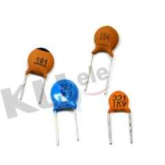
|
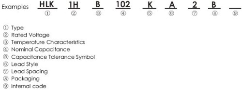
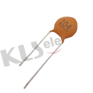
KLS10-HLK-DC50V-Y5P-102-K |
|
|
|
2.SPECIFICATIONS
| Item |
Specification |
| Capacitance |
100pF~22000pF |
| Capacitance Tolerance |
K(±10%),M(±20%),Z(+80%-20%) |
| Operating Temperature |
-25~85℃ |
| Temoerature Characteristic |
Y5P、Y5U、Y5V |
| Rated Voltage |
50~160,250,500VDC |
| Dissipation Factor(tgδ) |
tgδ≤2.5%
@ 1KHz,1±0.2Vrms,25℃ |
| Voltage Proof |
2.5Ur |
| Insulation Resistance(IR) |
IR≥10000MΩ @ 25℃,the rated voltage |
| Testing Voltage |
3 times the rated voltage |
|
|
3.CAPACITANCE CHART
Rated
Voltage |
Dimension |
Temperature Characristic |
Lead Size |
| Y5P(B) |
Y5U(E) |
Y5V(F) |
| Diameter |
Thick |
Nominal
Cap. |
Plate
Size |
Nominal
Cap. |
Plate
Size |
Nominal
Cap. |
Plate
Size |
Space |
Diameter |
| 50~160 |
5.0 |
3.0 |
221~152 |
4718 |
152~502 |
4718 |
222~682 |
4718 |
2.5±0.8 |
0.40±0.05 |
| 5.5 |
182~222 |
5018 |
682 |
5018 |
103 |
5016 |
| 6.5 |
252~332 |
5818 |
822~103 |
6018 |
103 |
6020 |
5.0±1.0 |
0.45±0.05 |
| 7.5 |
472 |
6818 |
|
|
|
|
| 8.0 |
502~562 |
7518 |
|
|
|
|
| 9.0 |
682 |
8520 |
|
|
153~223 |
8220 |
0.53±0.05 |
| 10.5 |
822~103 |
9820 |
|
|
|
|
| 500 |
5.0 |
4.0 |
151~561 |
4835 |
102~222 |
5040 |
|
|
5.0±1.0 |
0.45±0.05 |
| 5.5 |
681~102 |
5035 |
|
|
222~332 |
5040 |
| 6.0 |
122 |
5535 |
|
|
|
|
| 6.5 |
152 |
6035 |
272~392 |
5840 |
392~562 |
6040 |
| 7.0 |
182 |
6535 |
|
|
|
|
| 7.5 |
222 |
7035 |
472~502 |
7040 |
682 |
7040 |
| 8.0 |
272 |
7535 |
682 |
7640 |
|
|
| 8.5 |
|
|
|
|
822~103 |
8040 |
| 9.0 |
332 |
8435 |
|
|
|
|
0.53±0.05 |
| 9.5 |
392 |
8835 |
822~103 |
9035 |
|
|
| 10.5 |
472 |
9835 |
|
|
223 |
9530 |
| 12.5 |
682 |
11535 |
|
|
|
|
| 14.5 |
103 |
13535 |
|
|
|
|
| Capacitance Tolerance |
±10,±20% |
±20% |
80/-20% |
|
|
| Packing Style |
Bulk,Taping |
|
|
|
| 4.Class Ⅱ Ceramic Capacitors
Codes consists of 3 digitals,where the first 2 digitals indicate the lowest temperature and the highest temperature separatly,and the last digital indicates the maximum capacitance change over temperature range from 25℃.
● Class Ⅱ & Ⅲ Temperature Characteristic Chart
First digital is the
lowest temperature |
Second digital is the
highest temperature |
Last digital is MAX capacitance
change over temperature range from 25℃ |
|
|
| 4 +65℃ |
| 5 +85℃ |
| 6 +105℃ |
| 7 +125℃ |
| 8 +150℃ |
|
| A ±1.0% |
| B ±1.5% |
| C ±2.2% |
|
D ±3.3% |
|
E ±4.7% |
| F ±7.5% |
| P ±10% |
| R ±15% |
| S ±22% |
| T +22% -33% |
| V +22% -82% |
| U +22% -56% |
|
●Temperature Characteristic Chart
EIA Code/
International Code |
NP0 |
N150 |
N220 |
N470 |
N750 |
SL |
Y5P |
Y5U |
Y5V |
| GB Code |
CH |
PH |
RH |
TH |
UJ |
SL |
2B4 |
2E4 |
2F4 |
●Temperature Characteristic and Capacitance Tolerance Chart
Temperature
Characteristic |
Capacitance Tolerance |
| K |
M |
S |
Z(P) |
| Y5P |
√ |
× |
× |
× |
| Y5U |
× |
√ |
× |
× |
| Y5V |
× |
× |
√ |
√ | |
